A hardware simulation of 4-bit numbers adder.
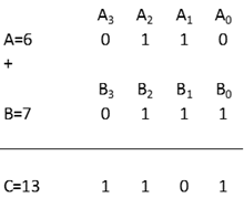
How the addition operates in binary – example: 6 (A)+7 (B) = 13 (C):

Below is a hardware logic diagram of a full adder, which is used to do 1-bit additions. It uses 5 logic gates, each made out of 4-6 transistors.

There are also other ways to combine different logic gates to produce a full adder.
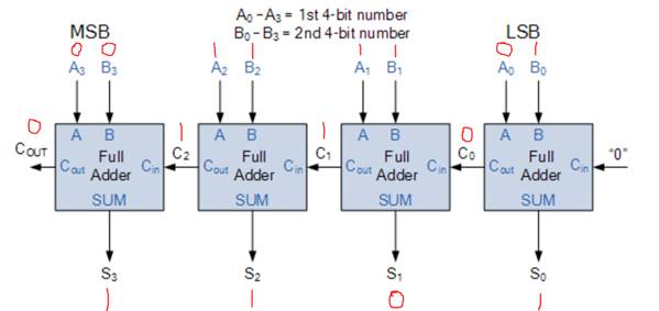
To operate 4-bit additions, it requires roughly 4 full adders connecting like below.

It starts by adding the lowest digits of the two binary numbers and an initial carry 0. When the sum is no more than 1, it will set the result digit to the sum. When the sum is above 1, it carries 1 into the upper digits adder, and keep the reminder as the result digit.
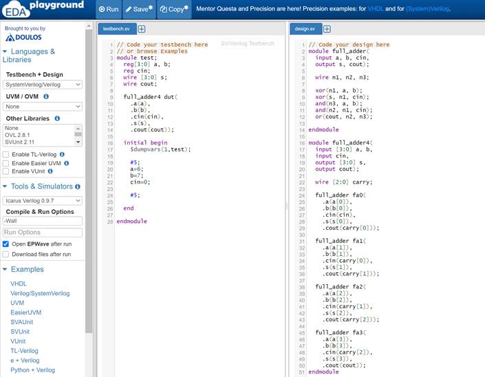
I used an Electronic Design Automation (EDA) software describing the circuit with Verilog (a hardware description language). It can be programmed into a FPGA (Field Programmable Gate Array) and physically form the logic gates by connecting the circuit with the embedded transistors and wires.

This is a micro reflection of how computer chips are designed/produced. Modern computer chips have tens of billions of transistors, and wire them together in a tiny board, taking care of the interference between the components and the amount of heat they generate.